One 8 pin IC, 6 resistors and a LED :-) for high performance RIFE applications
Frex-PFA-2 is an upgrade to the FreX-PFA-1 (do-it-yourself) circuit that makes an excellent high performance RIFE Frequency Therapy contact instrument. This tutorial is a step by step instruction on how to build your own high performance contact pad system for around $30.
FreX-PFA-2 output signal is a first class biological signal for RIFE use. We have high performance square waves that generates high frequency sine wave harmonics allowing us to target all of Dr Hulda Clark and Dr Rife's frequency range. Between 300,000Hz to 1.6MHz
Only 1 x 8 pin DIP IC and 6 resistors and a LED are used and insert into a simple to use bread board. A tiny bit of soldering is required for the contact leads, no soldering of the circuit is needed.
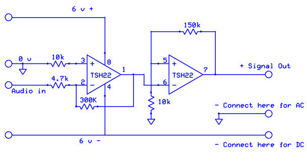
FreX-PFA-2 uses the TSH22IN, High Performance dual powered operational amplifier. It will run from 3 VDC to 36 VDC, and has a 25MHz bandwidth, making it ideal to generate those very fast square waves which are so important to this application. You will easily be able to configure it for AC or DC applications.
Numerous health authorities working in this field only use DC signals for pathogen elimination, Dr Hulda Clark is a well know authority with pad systems as well as Dr Richard Loyd, who is an expert at both Rife and Clark applications. Dr Richard Loyd has commented that 10 VDC is as potent as 200 VAC.
FreX-PFA-2 Schematic
FreX-PFA-2 Parts List
Mouser.com is a good source for the TSH22IN Operational Amplifiers - I have used JayCar USA to source all the other components.
Soldering: Can't get away from it entirely. The zero and plus leads of the 3.5mm audio lead need to be inserted into the bread board and the best way of doing this is by lightly tinning them with solder. The two alligator clips that attach the metal tubes to the audio lead also need soldering. If we get the large alligator clips with screws, these have too tight a clamp on the electrodes and we want the electrodes to easily come away from the leads for those accidents us humans often have.
Total comes to $24.17 and when we add postage, audio leads and metal tubes, then we should get out of it for around $30
... Now, lets build it :-)
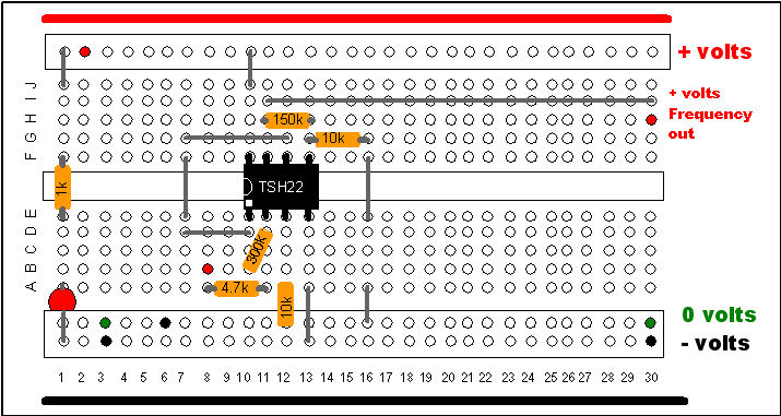
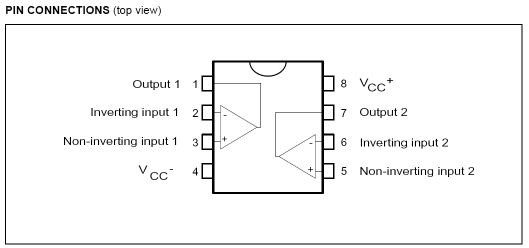
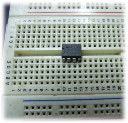
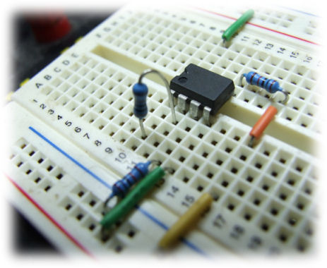
Insert the THS22IN as shown with pin 1 on the bread board position E:10
You can use sold wire or circuit jumpers as I have used to make connections.
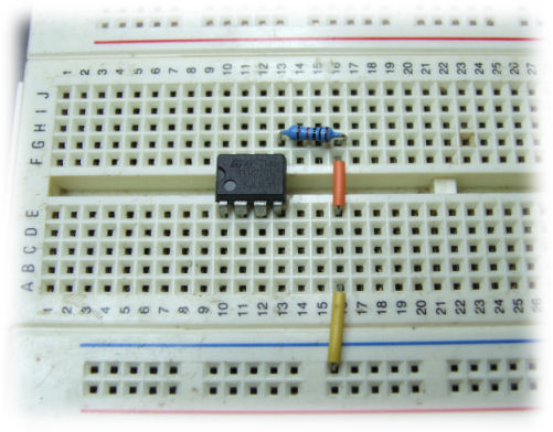
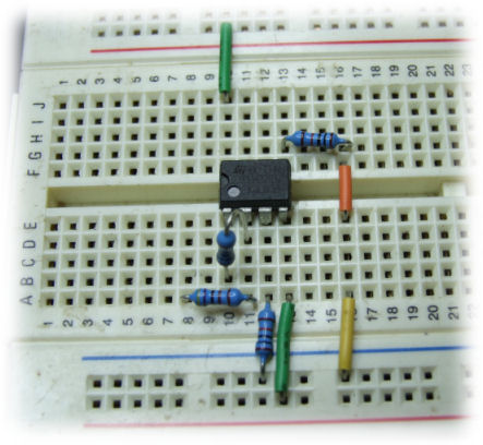
The yellow jumper goes from 0 volts to A:16
The orange jumper, jumps over to the upper side of the board connecting E:16 to F:16
The 10k resistor connects G:16 to G:13
This grounds pin 5 of the TSH22IN via this resistor
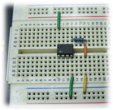
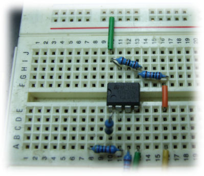
Here we connect the voltage rails to the TSH22IN.
Connect the green wire from - (minus) volts to A:13 which is pin 4 on the TSH22IN
Connect the other green wire + (plus) volts to J:10 which is pin 8 on the TSH22IN
You may need to use a small needle nose pliers to help insert these wires
You can print this tutorial so you can easily reference the bread board positions in the above diagram
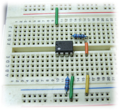
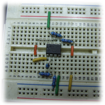
Here we connect a 10k resister from 0 volts to A:12. This anchors the TSH22IN pin 3 to 0 volts.
Now the 300k ohm resistor is positioned connecting B:10 to D:11
Notice how I have bent the resistor to fit into a close gap. Good practise to keep your FreX-PFA-2 circuit neat as we don't want resistors on long leads, poking up, ready to be knocked by something, thus coming loose
This resistor is the pre-amplifier value, and allows for a low 10mV audio signal to be substantially amplified, and prepared for squaring. It connects pin 1 and pin 2 together on the TSH22IN
Next we insert the 4.7k ohm resistor at A:11 to A:8
The audio frequency from the computer, etc. will come through here and provides impedance matching for the audio signal and the TSH22IN
Now for the squaring function on the second amplifier. The 150k ohm resistor is inserted at H:11 to H:13 connecting pin 5 and pin 7 of the TSH22IN
The pre-amplifier does a really nice job of getting the frequency wave form moving, and when it enters the second amplifier, it gets forced up very quickly giving us very good rise and fall times on our square wave. This is where our harmonics get generated.
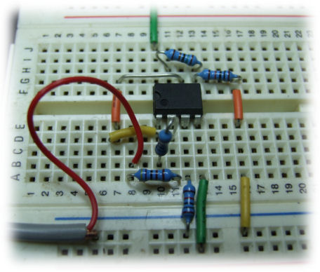
Last part of the actual circuit. Here we connect the pre-amplifier to the squaring amplifier. Three wires do the job.
2. The orange jumper on the left connects F:7 to E:7
3. The yellow jumper connects D:7 to D:10
An error appeared here and was changed on 10th June 2008. It said pin one connected to pin five on the TSH22. The photo was right, pin one actually connects to pin six, not pin five. Sorry for the confusion.
If you get lost, in what is new in each photo, just scroll up to the photo above and you'll see what is added :-)
We are really getting close to testing out our new high performance RIFE machine.
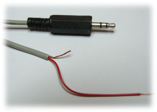
Take the 3.5mm stereo audio lead and cut one end off with wire cutters, and shred back the plastic insulation to expose the wires. Most 3.5mm audio leads have two leads connected together, We only need one of these leads as FreX outputs the same signal on both channels.
We need access to the shielded wire (the outer wire), and the active wire, which will be cased in its own insulation. Usually colored red and white. Nice to use the red color as this denotes an active plus wire.
After preparing them in similar fashion as we have in the photo, give the copper wires a little twist to make sure they are compacted together, ready for soldering.
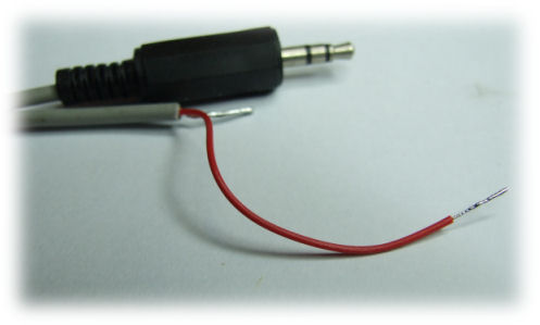
Now we have soldered the audio wires they should look something like mine in the photo
They are now ready to be inserted into our FreX-PFA-2 circuit
Place the 0 volts (audio common/shield) into the 0 volts line.
Insert the red audio active wire into B:8
You may need to use needle nose pliers to firmly secure these wires.
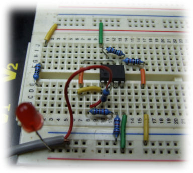
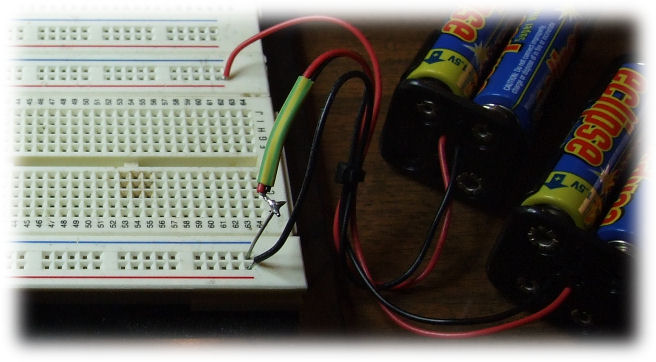
Adding a Red LED to let us know the circuit is active and has power.
Insert a jumper from the + (plus) volts rail to J:1
Insert the 1k ohm resistor over the gap at F:1 to E:1
The LED wire with the long pin is the + pin. The short pin, closest to the flat cut out bevel in the LED plastic case is the - (minus) pin. We have to get this right otherwise we can destroy the LED, or it just wont work, can be frustrating.
Insert the plus (+) pin into A:1 and the minus (-) pin into the minus volts rail. Do not connect the minus pin to 0 (zero), as this will draw power unevenly from the rails and will effect the output signal wave shape a little. We want to place an even load on both battery supplies, so this is how we do it.
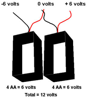
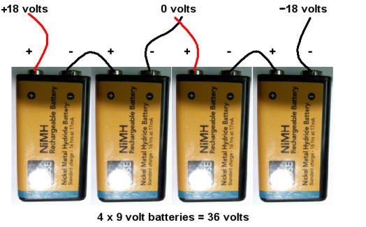
Creating a dual battery power supply is quite easy, and will provide you with numerous power configurations. If using DC connections, then we don't want to go above 15 volts, otherwise burns will happen. I like to use 12 volts for DC applications. If wanting to use AC, then we can go a little higher, and two or four 9 volt batteries can be used to give us 18 VAC or 36 VAC. I will show you have to utilize both types of signals here. But first, lets assume we are wanting to configure a 12 volts supply for DC use.
Simply take a red and back wire from both battery snap packs, twist or solder together and this is it. You can see in the diagram to the right how the voltages are made available.
Here we have 4 x 9 volt batteries providing 36 volts supply if using alkaline batteries, or around 32 volts if using chargeable batteries.
Second last step. Here we simply connect the batteries to our FreX-PFA-2 circuit.
The red plus battery lead inserts into the red plus voltage rail.
The joned red and black battery wire (0 volts) is inserted into the 0 volts rail.
The black negative (-) battery lead is inserted into the bottom red (minus) voltage rail.
If we have put the together correctly, the red LED will come on.
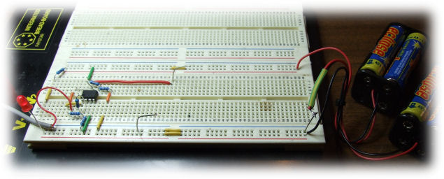
Step 16
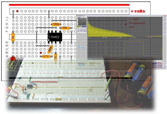
Here we have it, up and running. The two wires sticking up in the board is how we connect meters to test the circuit.
The red long jumper on the bread board connects I:11 (frequency out) to a place down the board where we insert the output lead to the + (plus) electrode. If the long signal lead inserts at say I:30, then connect the plus (+) electrode wire to to H:30
The minus volt electrode connects to 0 volts for AC applications, or connects to - volts for DC applications close on the rail where the battery leads were inserted.
To switch off the circuit, just pull the battery leads out and secure the tips to make sure they don't touch and short, which would very quickly kill the battery life.
The 0 volt rail = AC or bipolar output (traditional Rife therapy)
The (-) volt rail = Pulsed DC Positive Offset output (Hulda Clark regime)
When looking down on your circuit, you will see it resembles our bread board layout except for the long wire connected at i11 to i30.
i11 is the second TSH22IN amplifier output and the one we use for the (hot) (+) volts wire electrode.
Good idea to to connect a long wire from i11 to i30 to bring this (hot) positive charged signal up to the right side of the bread board, away from the other components.
Speaker wire makes good electrode leads for this audio circuit. Six to ten feet should be enough. We can expose 10mm of the wire end, twist it and insert it into H30. This will be the (hot) positive lead and is marked as red.
The other speaker wire needs to be inserted to either the (-) minus volts rail at the bottom of the bread board, or the (0) volts rail just above the (-) volts rail. This will be the black electrode and ground/minus volts reference depending on what type of signal you want to output.
The Red LED MUST come on when power is connected, otherwise the circuit is NOT working.
Connect the 3.5mm stereo lead to your computer headphone or speak output. Run FreX and output a frequency around 500Hz.
Depending on your battery set-up, gently touch the electrodes and see if you get a tingle. If not, wet your hands in saline solution and grab the electrodes. You should now have confirmation of it working.
If you have a multi meter with a Hz function, simply connect it to the + and - outputs and check the frequency. The nature of this circuit is it is working 100% or it isn't working at all. Set all computer volumes to around half, if you can hear it out the computer speakers, then it will work.
It is an easy and very simple circuit to build, and is very rugged. The TSH22IN has lots of protection inbuilt into it, so not much can go wrong with this circuit so long as you have multiple checked your connections to the diagrams. Errors can occur when a component is not making the connection of the pins in the bread board. So giving them ALL a gentle wiggle will help reduce faulty connections here.
If you are still unsure, feel free to take a digital photo of your handy work, making sure it is a clear photo and send it to me and I'll have a look at your circuit. I need to be able to read the numbers on the bread board.
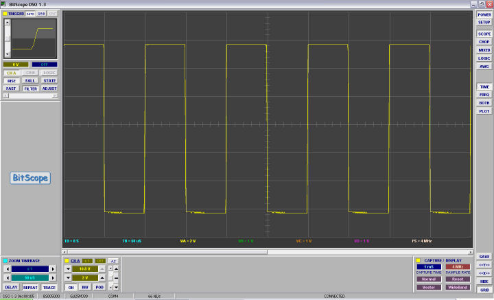
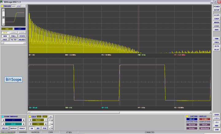
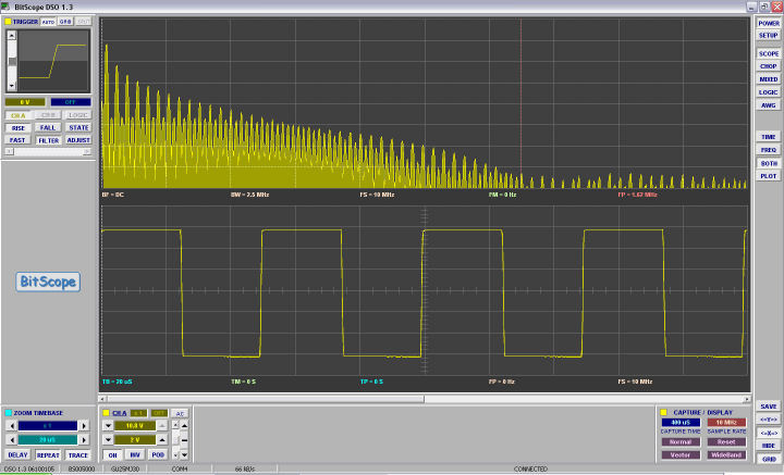
Here are some oscilloscope and spectrum images of the FreX-PFA-2 signal
10,000Hz AC signal on a 2.1 GigaHertz Bandwidth Oscilloscope - very nice square waves.
10,000Hz AC with spectrum - harmonics good to 1.5MHz
20,000Hz AC with spectrum - harmonics good to 1.65MHz.
e-mail Ken
The information provided on this site is for informational purposes only and is not intended as a substitute for advice from your physician or other health care professional or any information contained on or in any product label or packaging. You should not use the information on this site for diagnosis or treatment of any health problem or for prescription of any medication or other treatment. You should consult with a health care professional before starting any diet, exercise or supplementation program, before taking any medication, or if you have or suspect you might have a health problem. You should not stop taking any medication without first consulting your physician.
WARNING
When this circuit is made in Australia, it can only be used for veteniary and homeopathic purposes. This is to comply with TGA regulations which state all medical electrical devices that produce physiological effects on humans must be licensed.
Step 1
Step 2
Step 3
Step 4
Step 5
Step 6
Step 7
Step 8
1. The silver wire connects G:12 to G:7
Here we have joined pin 1 and pin 6 of the TSH22IN together. The pre-amplified signal goes out pin 1 and enters the second amplifier on pin 6
Step 9
Step 10
Step 11
Step 12
Step 13
Step 14
IMPORTANT : Always use the same type of batteries with the same charge, do not use slightly used batteries with new batteries. It is important that when we install batteries they carry all the same charge and are of all the same type.
Step 15
Step 17
Connecting Electrodes
Is It Working ?
Last updated 18th December 2011
Copyright 2008-2012 Ken Uzzell - ALL RIGHTS RESERVED