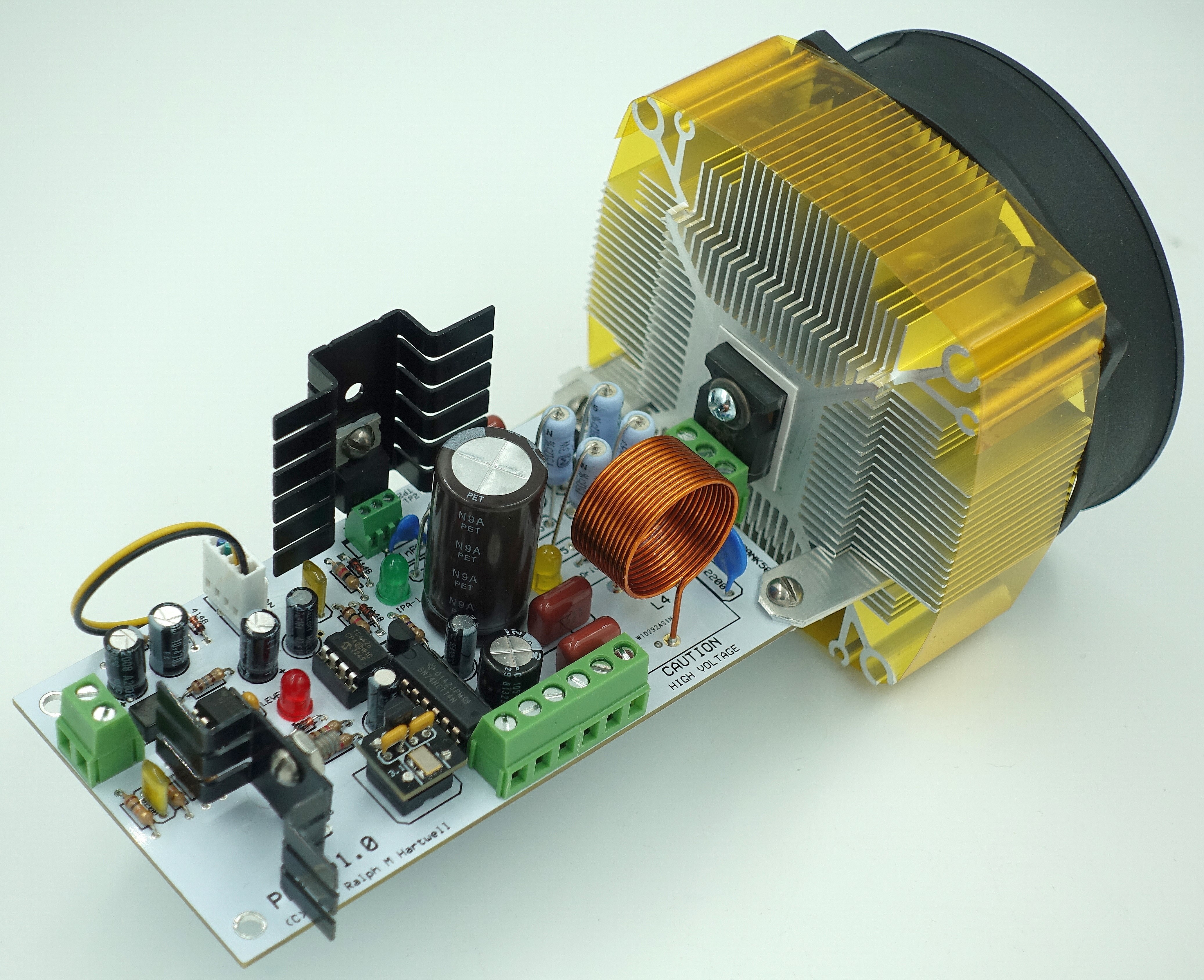
PA4 Rife Plasma Tube Amplifier with HS5 Heat Sink and Fan
Works with virtually any input signal source.
( Click on the picture for a larger view )
The PA4 can be supplied with your choice of either 3.1 MHz or 3.3 MHz carrier frequency oscillators.
Complete technical details and setup
information for the PA4 are available in the
Instruction Manual.
Overview -
- The PA4 is not a conventional RF power amplifier. It will not accept an RF drive signal from a conventional transmitter or exciter. The PA4 is a fix tuned, high frequency, Class-E, switch mode amplifier.
- The modulation signal source for the input to the PA4 may be any stand-alone frequency or signal generator, such as an F165, a GB-4000, a Spooky 2, or a similar unit. Because of the exceptional input sensitivity of the PA3, signal sources such as cell phones, CD players, and computers may also be used with the PA4.
- Modulation frequencies between 0.4 Hz and 200,000 Hz may be used with the PA4.
- The PA4 has an on-board 3.1 MHz carrier oscillator module which may be swapped for an oscillator module of a different frequency should this be required.
- The optimum operating frequency for the PA4 is 3.1 MHz,
however, it will operate across the carrier frequency range
of 2.7 to 3.5 MHz. Operation outside this frequency range
may cause serious damage to the PA4.
PA4 TECHNICAL SPECIFICATIONS:
DC Power Supply:
- For the Power Amplifier: +25 to +190 volts DC at a maximum current of 3.0 amperes; nominal operating current less than 2.1 amperes, depending on output power level and modulation duty cycle.
- For the Signal Processor and heat sink fan: +18 to +22 volts DC at a maximum current of 750 mA with 100% duty cycle modulation.
Input Impedance:
AC coupled, approximately 200 Ohms.
Input Drive Signal Requirements:
- The Frequency range for any type of input signal waveform is 0.5 to 200,000 Hz.
- The Input signal voltage range is 0.3 to 10.0 volts peak to peak or .011 to 4.04 volts RMS.
- The Input signal waveforms are Sine, Square, Triangle, Trapezoid, and Ramp.
- Note that when using a square wave input signal, the duty cycle of the modulated RF output from the PA4 will follow the duty cycle of the input square wave. NOTE – Please do not exceed 50% positive duty cycle when using a square wave to prevent possible amplifier damage.
- VERY IMPORTANT - The input signal MUST be AC only, and there should be no DC offset voltage on the input signal. If a DC offset voltage is present it is possible for the modulation control circuit of the PA4 to malfunction so that when the input signal is turned off, the PA4 may suddenly turn on with 100% carrier output. This will result in twice the rated average amplifier power being delivered to the plasma tube. This may cause plasma tube or failure of the STW20NK50Z output transistor.
Precharge “Warmup” Time:
- After +19 volts is applied to the PA4, a precharge time is required before the signal processing circuit is stable and ready to generate a 50% duty cycle square wave. The amount of time varies with the applied input voltage. The times listed below are typical of the PA4.
Input Volts Input Volts Precharge Time
Peak to Peak RMS in Seconds
0.3 0.11 90
0.4 0.35 30
10.0 4.07 10
Carrier Frequency:
- Within the limits of 2.7 to 3.5 MHz. Operation outside of this frequency range may cause damage to the PA4. The suggested operating frequency is 3.1 or 3.3 MHz. The PA4 is supplied with a standard 3.10 MHz oscillator, but customer selected frequencies may be specified at the time of order.
RF Power Output:
- Up to 500 watts peak power or 250 watts average power into a 50 ohm dummy load when the carrier is modulated by a 50% duty cycle square wave with frequencies from 0.4 to 200,000 Hz.
- When the PA4 is operated at a peak power level of 300 watts or less, the PA4 may be operated at any duty cycle between 0 to 100%.
- The power output of the PA4 is adjusted by varying the high voltage DC supplied to the PA4.

This web site and all contents including pictures, text and diagrams is Copyright 2012 - 2026 by Ralph M Hartwell.
All Publication, Reproduction and Manufacturing Rights Reserved.