The SSQC Signal Adapter
The SSQC is a general purpose audio signal processor board. The function of the SSQC is to take signals within the frequency range of 1 to 200,000 Hz and convert them to fast rise time square wave signals
The SSQC allows the operator to use a computer sound card, cell phone, MP3 player or similar device to drive a device such as the Spectrotek Services PA3 amplifier or any similar device that will accept a +5 Volt square wave drive signal.
Input signals to the SSQC may be sine, triangle, trapezoidal, or square wave. The circuit will ignore slow to moderate changes in the amplitude of the input signal, and will continue to produce a clean square wave output signal.
The output signal from the SSQC is DC coupled, and the output is reasonably protected against reverse voltages from external sources.
Shielded cable should be used for both the audio signal input wiring and the output voltage wiring from the SSQC to the PA3 amplifier to prevent RF interference pickup when the SSQC is used in close vicinity of an operating plasma tube amplifier system.
If desired, small diameter 50 Ohm impedance coaxial cable may be used for both the input and output wires. The length is not important, except that shorter cables will reduce the possibility of unwanted RF interference with the operation of the SSQC.
The SSQC has a high frequency roll off designed into its circuitry such that the SSQC is virtually “deaf” at frequencies above 1 MHz, thereby greatly reducing the possibility of RF interference from 3.1 MHz plasma tube amplifier systems. However, if the local RF environment from the plasma tube equipment is powerful enough, the RF interference may overpower the desired input signal and cause the SSQC to output erroneous signals to the connected device.
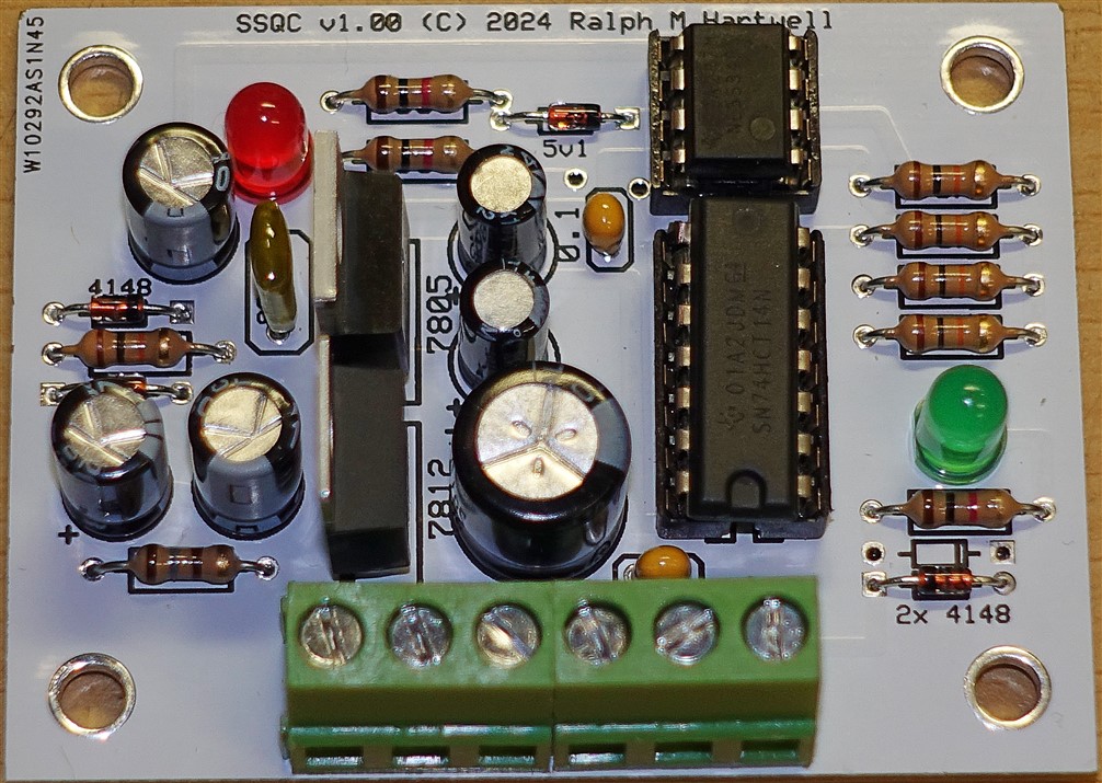
The SSQC has two indicator diodes for operator convenience. When the Red LED is illuminated, this indicates that the input signal is active and is being converted into a square wave. When the Green LED is illuminated, this indicates that the square wave output signal is present at the output of the SSQC.
SSQC TECHNICAL SPECIFICATIONS
POWER REQUIREMENTS
Voltage: +15 to +25 Volts DC
Current: With no input signal, 11 mA
With input signal, no load, 17 mA
With input signal and 470 Ohm load, 22 mA
With input signal and 100 Ohm load, 40 mA
With input signal and 50 Ohm load, 60 mA
With input signal and output shorted, 138 mA
TIME TO STABLE SQUARE WAVE OUTPUT AFTER POWER ON ~ 60 seconds.
If an input signal is present as the SSQC stabilizes, the duty cycle of the output square wave will slowly increase from about 20% to the normal 50%. However, it does not matter whether or not the audio input signal is present during stabilization.
INPUT SIGNAL
The input impedance of the SSQC is ~ 200 Ohms.
Normal operation is over the voltage range of 600 mV to 5000 mV (0.6 V to 5.0 V.)
Voltages below 600 mV may work across a narrower range of frequencies but with some variation in the output duty cycle percentage.
FREQUENCY RANGE AND OUTPUT DUTY CYCLE
For an input voltage of 600 to 5000 mV and an input frequency from 1.0 Hz to 200 KHz.
With Sine wave input – The output duty cycle will be 50% +/- 2%.
With Triangle or ramp wave input – the output duty cycle will be 50% +/- 3%.
With Square or pulse wave input – the output duty cycle will be track the duty cycle of the input signal.
OUTPUT VOLTAGE
The SSQC is designed to drive loads from 50 to 1000 Ohms. The output voltage for various loads is:
With 1000 Ohm load 4.98 Volts Peak.
With 470 Ohm load 4.90 Volts Peak.
With 100 Ohm load 4.64 Volts Peak.
With 50 Ohm load 4.28 Volts Peak.
The rise and fall time of the output signal is 12 nS or less across the specified load impedance.

This web site and all contents including pictures, text and diagrams is Copyright 2012 - 2026 by Ralph M Hartwell.
All Publication, Reproduction and Manufacturing Rights Reserved.