Spectrotek Services 
Current as of 25 November 2025
Side Electrode Wires for the SSQ-BAT Plasma Tube
Important Note - Even though
this document shows the use of adhesive to hold the side wires
against the plasma tube, most researchers have found that
using a length of transparent Kapton tape with a width of
about 25mm is easier and works better than using adhesive.
By adding a pair of side electrode wires, the initial firing voltage of the SSQ-BAT is reduced.
If you are using an SSQ-BAT, this modification is strongly suggested to help prevent amplifier damage.
This change in electrode configuration helps to protect the PA1, PA2, PA3, or SPA4 amplifier from excessive tank circuit voltage that is generated when the amplifier is producing RF output power but the plasma tube has failed to light immediately. This may happen when using high modulation frequencies or when the duty cycle is short. A short duty cycle may be caused by a combination of simultaneously running modulation frequencies that combine to produce very short output pulses. When this happens, the plasma tube may fail to light during part or all of the RF output pulse from the amplifier. This failure to of the tube to light may cause amplifier failure, with the destruction of the STW20NK50Z MOSFET in the amplifier.
The reason for this failure to light immediately is due to the lack of ionized gas present when the tube is not turned on. Because it requires some milliseconds for all of the ionized gas to in the tube recombine after the power to the tube is turned off, the tube will normally light properly once it has gone into conduction, as long as the OFF time is substantially less than the ion recombination time. However, when the tube is first turned on, or if the OFF time between modulation pulses is long enough, the number of available ions in the tube will have fallen so low that the tube becomes non-conducting. As a result, it will require a much greater applied RF voltage across the tube electrodes to light the tube for the first modulation pulse than it will for subsequent pulses.
Should a series of very short pulses be applied to the tube when it has not been conducting previously, it is quite possible that the tube may fail to light at all during the series of short pulses. This failure to light will create very high voltages across the amplifier, and may cause MOSFET failure. These failures can be extremely difficult to trace, since they tend be intermittent and random. A system that has been functioning perfectly for an extended period of time may suddenly experience one or more MOSFET failures within a short interval. The addition of the side electrode wires as described here will virtually eliminate this problem.
No adjustment or tuning of the LC31 coupler is required in order to add these side electrode wires.
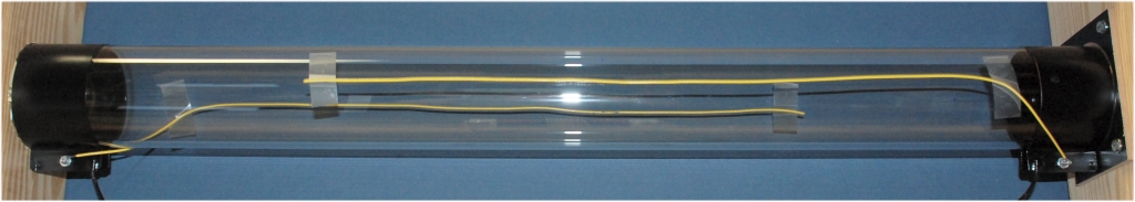
SSQ-BAT with side electrode wires temporarily installed with adhesive tape for testing.
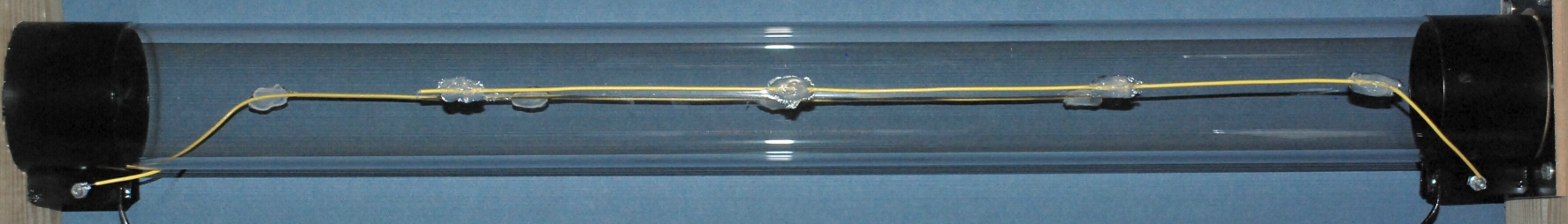
SSQ-BAT with side electrode wires permanently mounted in place using Silicone adhesive.
The wires should be insulated. Teflon insulation is ideal from the standpoint of heat resistance, but any type of heat resistant insulation is OK. Bare wires should not be used because the RF voltage on the wires may become high enough where the wires touch the tube to cause localized overheating of the tube wall. This may cause the glass to crack at that point, ruining the tube. The insulation on the wire will space the wire far enough from the tube wall to reduce the electrical and heat stress enough to prevent tube damage. The wire used here is AWG 22, but any wire from AWG 24 to AWG 10 should work as well.
The wires should run on opposite sides of the tube, directly across from each other. It does not matter where they are placed, side, top, bottom, or wherever, just place them across the tube from each other. The wires should extend about three-quarters of the distance from one electrode to the other.
For these photos, the wire was held in place with plastic tape. If you have tape which will tolerate 100 C temperature without melting or loosening, then using tape will work OK. On my tube, I used Silicone seal adhesive, which will withstand high temperatures. I used several strips of tape to hold the wires in place against the tube, and then applied four blobs of the adhesive to hold the wire against the tube. The tape was removed 24 hours later after the adhesive had hardened. Do NOT use an adhesive which is not flexible when it has hardened. A non-flexible adhesive can cause the glass of the tube wall to spall when it gets hot. This may result in a shattered tube.
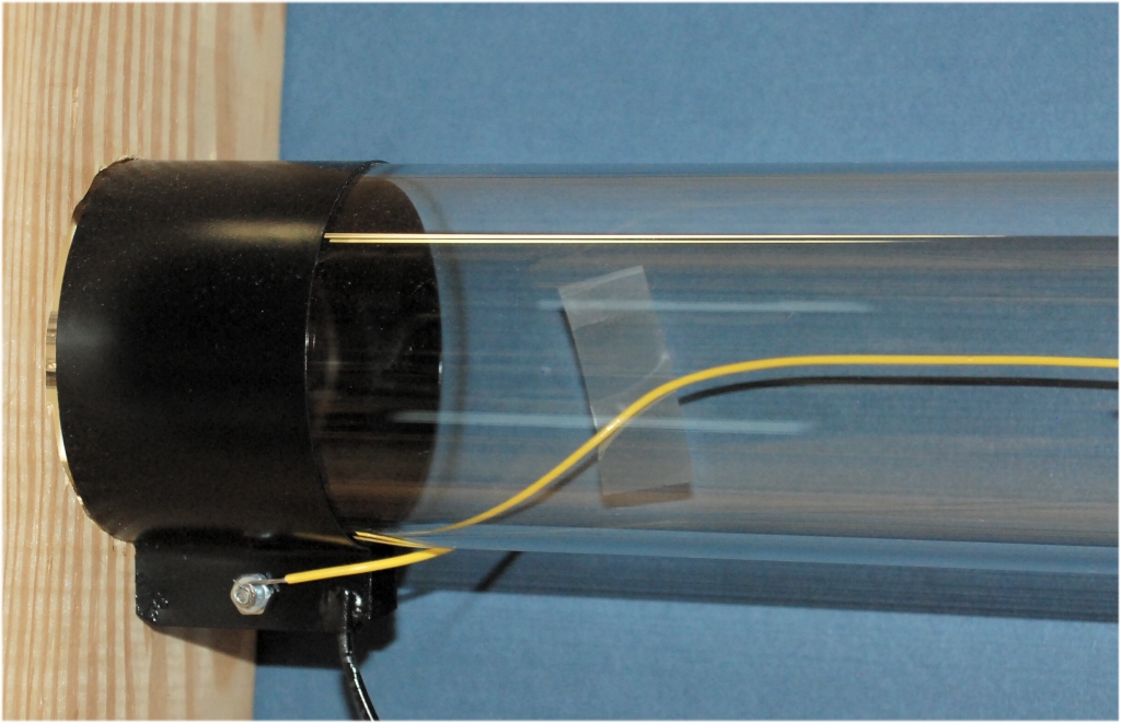
Orientation of the side electrode wire on the left side of the plasma tube.
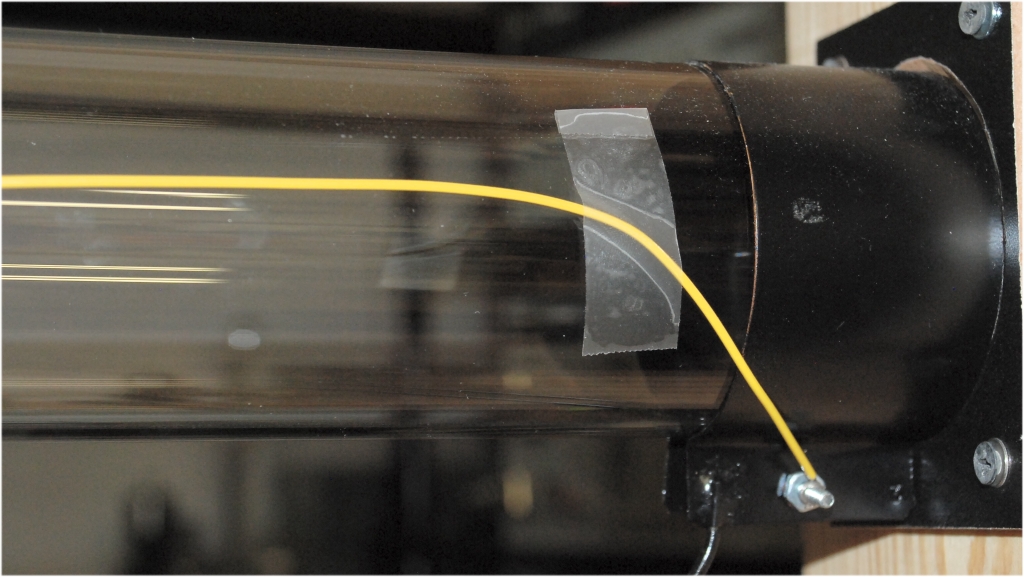
Orientation of the side electrode wire on the right side of the SSQ-BAT plasma tube.
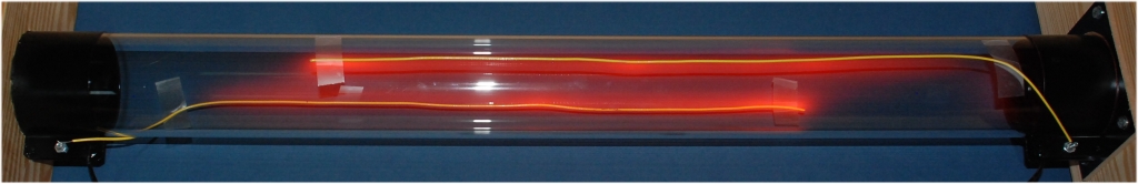
SSQ-BAT running with an amplifier voltage of 19 volts. Power is about 5 watts peak power.
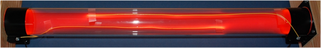
SSQ-BAT running with an amplifier voltage of 38 volts. Power is about 80 watts peak power.
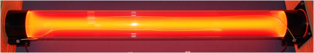
SSQ-BAT running at an amplifier voltage of 114 volts. Power is about 250 watts peak power.

This web site and all contents including pictures, text and diagrams is Copyright 2012 - 2026 by Ralph M Hartwell.