A New Matching System for Plasma Tube Systems
Specifically designed for use with the SSQ-2F and all Spectrotek Amplifiers
First posted on February 5, 2012
Overview
The use of commercially available RF power amplifiers to drive plasma tubes has been a common procedure ever since Dr. James Bare developed his Bare/Rife plasma tube system. That system, as do most systems, operates on the US Industrial, Scientific and Medical (ISM) frequency allocation of 27.120 MHz. The basic configuration of such systems, is shown in this block diagram:
Most commercial RF amplifiers that have been used thus far have been CB power amplifiers that have been modified to function in continuous duty operation. This usually involved adding one or more fans to cool the heat sink of the amplifier and the ferrite cores in the RF power circuitry of the amplifier. These amplifiers have been used because they will operate efficiently on the ISM frequency of 27.120 MHz, which is close to US CB channel 14, located at 27.125 MHz. This permits the amplifier to be built using mass-produced RF transistors and ferrite cores.
While this allows the manufacturer to supply a low-cost amplifier and still make a profit, it does limit the effective bandwidth of the amplifier. Most CB amplifiers, especially non-broadband units, will not operate properly at frequencies outside the normal CB band of 26.965 to 27.405 MHz. Many of the popular Rife frequencies, such as 2.X and 3.X MHz, are located outside of the frequency range of most CB amplifiers. While some of the available CB amplifiers will operate at those frequencies, many of them do not have the proper ferrite cores to function at low frequencies without failure. Other amplifiers, such as the High Frequency (HF) amplifiers produced by RM Italy have the correct ferrite cores to operate well at frequencies from 2 to 30 MHz, thus making them usable for plasma tube systems over a wide frequency range. Such amplifiers may be driven properly by the SSQ-2F Plasma System Controller.
Producing high power RF with an amplifier is one thing; coupling it efficiently to the plasma tube is another. The most common method of coupling the energy from the amplifier to the plasma tube is by using a commercially available antenna tuner, such as one of the MFJ series of tuners. While this method works, it has several drawbacks. First, tuners (actually, impedance matching systems) are not 100% efficient in transferring the RF energy from the amplifier to the plasma tube. Depending on the type of tuner, its adjustment, and local conditions, as much as 10% to 40% of the available RF power may be lost as heat in the tuner. In severe cases, internal tuner components such as coils, switch contacts, etc., may be damaged by overheating.
If you are going to use an antenna tuner, it is better to buy one that is too large rather than one that is too small. If you are using the "standard" modulation method where the RF carrier is modulated by a 50% on/off duty cycle square wave, then remember that the peak value of the RF power will be twice the average power level shown on your power meters. Because Ohmic losses increase as the square of the current, doubling the peak power will double the RF losses during the time the RF power is actually on.
Let's assume that
we have a 200 watt amplifier and an antenna
tuner that has an efficiency of 80%. During the time the RF
carrier is
on, the tuner will be able to pass 160 watts of power to our
plasma
tube and it will dissipate 40 watts of power as heat. We
could say that
our "effective" power to the plasma tube is 160 watts.
Because 20% of
the power is being wasted as heat, we would be able to
obtain the same
output to the plasma tube if we used a 160 watt RF amplifier
with a
100% efficient tuning system. So, in this case, the tuner is
reducing
the efficiency of our system.
But we are using a square wave modulation method, where the RF power is turned on 50% of the time and turned off 50% of the time. That means that once per cycle, the RF power is ramped from zero to full power and back to zero again. When the power is on for a very short time, as is the case with the usual modulation methods, the heating effect of the power will be more driven by the peak power level than the average power level.
If we were to drive our tuner with 400 watts of RF power, then we would have a peak power output to the plasma tube of 320 watts and we would be dissipating 80 watts of power as heat in the tuner. Since the cube root of 2 is approximately 1.26, we would see approximately 26% more heating effect in the plasma tube compared to the 200 watt system. 26% is the ratio of the cube root of the peak power to the peak power level of the 200 watt system (2:1.)
Thus, when driven at 400 watts, the 80 watt power loss in the tuner is costing us 1.26 times the 160 watts lost in powering the tube in our first example. That may not sound like much, but when we take into account that the power loss in the tuner is being increased from 40 watts to 80 watts, the tuner losses become 2.5 times as great at the higher power level than at the lower power level. That increased RF loss in the tuner will quickly become a heating problem in the tuner.
In general, it is far better to have a matching method that is as efficient as possible; that is, one that wastes as little power as possible in the matching system itself. A tunable antenna matching system based on a T-network does not fit that description.
Of course, if you do not need the full 300 to 400 watts of power that may be obtained from the typical RM Italy KL-300 amplifiers required to properly drive your plasma tube, you may be able to use a smaller, less expensive antenna tuner and simply ignore the additional losses. But that's not all...
The antenna tuners commonly used are manufactured for Amateur Radio service. That means they are designed to do two specific things. (1) match the 50 Ohm output of the transmitter to the unknown impedance of the antenna system, and, (2) eliminate harmonics of the RF carrier. For plasma tube use, matching impedance is great, but eliminating harmonics is not! When we are driving a plasma tube, we want the rise and fall times of the RF pulses to be as fast as possible, and the narrower the bandwidth of the matching circuit is, the slower will be the rise and fall times. In fact, the better the antenna tuner, the worse will be the rise and fall times because of the elimination of harmonics. An antenna tuner can only make an accurate impedance transformation on the specific carrier frequency it is tuned to; frequencies above and below the carrier frequency will be reduced in strength. This is not what we want to happen in a matching network. But we can fix that. Read on...
Eliminate the antenna tuner
The underlying use of an antenna tuner in an RF transmission system is to make the transmitter "see" a 50 Ohm resistive load even though the true load (the antenna) may be very different from 50 Ohms. The antenna tuner will perform an impedance transformation between the output of the transmitter and the input of the antenna system so that 50 Ohms is the effective load as seen by the transmitter. That works just fine for transmitting systems. When driving a plasma tube, however, the tube is not being used as an antenna.
While the plasma tube will radiate some RF energy, it is normally operating in an area where the RF radiated by the tube will be terminating in the body of the person being treated. That is done at a very short distance away from the tube. The amount of power lost in RF radiation is normally quite small. Therefore, we do not need an antenna tuner as used in a transmitting station. We just require a matching system that will efficiently transfer RF power from the transmitter to the plasma tube. This can be done by linking the transmitter to the plasma tube using a method very similar to the ones used for coupling a transmitter to an RF matching system step-up transformer.
Note that we are not talking about the RF output transformer that is used in some amplifiers. That transformer is built into the amplifier and is used to convert the low collector or drain impedance of the final RF stage to the 50 Ohm impedance of the output. The matching transformer we are talking about here is the one that converts the 50 Ohm output into a higher impedance suitable to drive the plasma tube.
We should note that we can link-couple a plasma tube directly to an RF amplifier that does not have an internal 50 Ohm output transformer. This is normally done by replacing the output transformer with a link coupling coil that is tuned to 3.1 MHz with a suitable capacitor. That method is beyond the scope of this discussion. What we will be looking at here is the way to couple a 50 Ohm RF amplifier to a plasma tube by using a matching transformer that is tuned to the operating frequency. For this discussion, we will be assuming that the RF output frequency is 3.1 MHz.
Let's look at the standard matching and coupling system that is used for most of the plasma tube systems on the market. This is the usual method used for driving a plasma tube at 27.120 MHz. In this case, an antenna tuner is used to match the 50 Ohm output of the amplifier to the plasma tube and coil assembly:
This system works, but has the characteristics of the antenna tuner system previously mentioned. Not only will there be power losses in the tuner, but the function of the tuner will be to reduce the actual bandwidth of the matching system. Using the antenna tuner is equivalent to having a rich "full-bodied" sound and then passing it through an audio graphic equalizer set for a narrow band peak.
To keep the audio analogy going, imagine that we are designing an audio system for a concert hall. In one case, we will attempt to maximize the bandwidth of the audio system, allowing all of the harmonics of the musical instruments to be transmitted to the listeners. In the other case, we will put a band-pass filter between the power amplifier and the speakers. This band-pass filter (in series with the amplifier) will be adjusted so that only the main resonant frequency of the musical notes is passed. All of the harmonics will be reduced in amplitude. Obviously, the sound produced will not be as "full-bodied" as the one where all of the harmonics are present. That describes what is happening when using a tunable antenna matching system with a plasma tube. The antenna tuner has been designed to act as a band-pass filter and it will function as such. We do not want it to act like this.
There is another problem with antenna tuners. The amount of impedance transformation from the 50 Ohm input to the antenna output is continually changing as the operating frequency is changed. The higher the operating frequency is, the greater will be the amount of impedance transformation in the antenna matching system. One could draw the analogy that an antenna tuner is "blind." It has no idea what the impedance of the antenna is. It merely looks at the impedance at the 50 Ohm input side and adjusts it so that the 50 Ohm input is always matched. A dangerously mismatched antenna may look just fine to the antenna tuner.
Therefore, when using an antenna tuner, one should keep an eye on several operating parameters, including the relative amount of RF power being applied to the antenna system and the amount of SWR at the input of the antenna system. It is possible to over-stress the antenna tuner and cause arcs or an over-temperature failure in the internal capacitors or coils.
One of the best ways to avoid excessive stresses in the antenna tuner is to use a tuner whose upper power rating far exceeds the maximum power we will be using. In many cases the tuners most suited for plasma tube use are those that are rated for 800 to 1000 watts.
Another problem in choosing the correct antenna tuner is that the loads the tuner will be looking at will vary over a wide range. For example, the effective impedance of an open-ended coil will be different from that of a straight plasma tube, which in turn will be different from the effective impedance of the same tube when it is operated with a phase-inverter circuit that allows both ends of the tube to drive the subject.
One of the problems with using an off-the-shelf antenna tuner is that it is almost impossible to know what loading conditions it will be asked to operate under. The tuner was designed to work into most properly functioning antenna systems. Using a tuner to match a plasma tube may drive the tuner outside its design limits if the impedance of the tube is too far away from the impedance range of the tuner. There is no way to calculate this when designing a plasma tube coupling system using an antenna tuner. The loads the tuner may encounter range from a tuned "Q" of 1 to upwards of several thousand. Since plasma tubes are often used for non-standard applications, such as high-intensity experiments, it is possible to encounter loading effects that are outside the range of the antenna tuner.
Any time the tuner is asked to perform with an impedance that is outside its design limits, there is always the danger that the tuner will not be able to match the full 50 Ohm operating range of the transmitter. That may cause the transmitter to see an abnormally high SWR at its output. It is possible for the protection circuits in the transmitter to reduce the output level so that the output transistor is not over-stressed. It is also possible that the protection circuits will not be able to handle that condition and the transistor may fail as a result.
There is another problem with most tunable antenna matching systems. The problem is that most of the tuners that may be used for plasma tube RF systems were never intended to be located physically near the plasma tube. Most antenna tuners were designed to be located near the transmitter or the transmission line that feeds the antenna system. That allows the tuner to be operated from a convenient location near the operator. That method works well with a normal antenna system, where the antenna is located far away from the antenna tuner.
With plasma tube systems, we normally want the power source to be located at some distance away from the subject who is receiving the plasma tube signal. In many cases, we desire that the power amplifier be located as far away as possible from the subject in order to keep the high fields away from people while they are being treated. This may require a fairly long run of coaxial cable between the amplifier and the matching system. While this works well enough at the usual antenna signal levels used, which are below 2 kW in most cases, it can be a problem when working with plasma tube systems. For our use, we will see that the preferred method is to locate the coupler and matched transformer system at the plasma tube. That way, the relatively low-level or medium-level RF signal from the amplifier can be applied to the coupler and the plasma tube will be receiving its full power without losses in the system.
In our case, the RF power is distributed to the plasma tube primarily by the electric field, with the magnetic field being secondary. For the best coupling, we wish to keep the electric field away from the subject as much as possible while keeping the electric field at the tube as high as possible. This will allow the subject to be in a lower field strength area as much as possible. This is why we often see the RF power amplifier located a fair distance away from the operator and the subject. While the magnetic field from the plasma tube and the coil may be fairly strong, the magnetic field drops off in strength at the square of the distance from the source, which is not as unfavorable as having a local source of strong radiation present in the area where the subject and the operators are located.
Keep in mind that the plasma tube is an RF radioactive device and excessive RF field strength must be avoided. It is desirable that the RF power system be built and operated so that the RF fields at the operator's location are kept as low as possible. This is why we prefer to keep the tuning system and the RF power amplifier some distance away from the operator. This is the case in many installations, where the amplifier and matching system are located some distance away from the treatment area.
A typical plasma tube system may have a power amplifier located at or near the system controller in one room, with a run of coaxial cable extending to the treatment room where the amplifier output is applied to a coupler and matching system that drives the plasma tube. That is the system we are dealing with here.
Designing your matching system
Enough of the theory. Let's look at how we can use a matching system that is more efficient and has controllable characteristics. This is the system that I am using at the present time. For this system, we will use a matching system that is based on a 3.1 MHz link coil coupler. This coupler is designed to be operated at powers of up to 300 to 400 watts when used at 3.1 MHz.
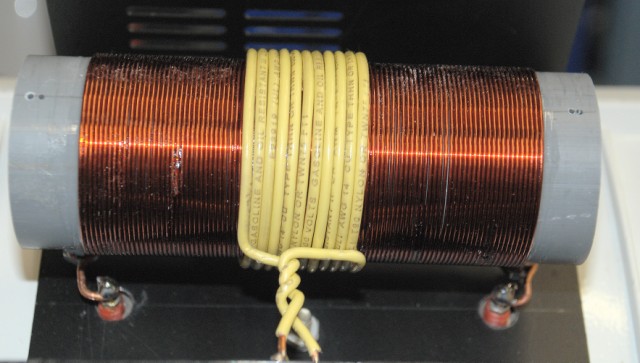
For our matching system, we will be using a link-coupled step-up transformer connected between the RF power amplifier and the plasma tube. In this case, the step-up transformer will be composed of the link coupling coil and the secondary coupling coil. We will be designing the transformer to have a fixed impedance transformation ratio between the amplifier and the plasma tube.
The step-up transformer consists of a primary coil and a secondary coil wound on a common core. The primary coil is a link coupling coil that is wound over the secondary coil. The primary coil is connected to the 50 Ohm output of the RF power amplifier. The secondary coil is connected to the plasma tube coupling coil and is designed to provide the proper voltage and current to drive the plasma tube at full power.
The design of the 3.1 MHz link coil coupler is described in detail in another article. We will assume here that the coupler has been properly designed and built, and that it has a known impedance ratio between the primary and secondary. For example, if the primary coil has 11 turns and the secondary coil has 94 turns, the turns ratio will be approximately 1:8.5 and the impedance ratio will be approximately 1:72. That means that a 50 Ohm load on the primary will look like approximately 3600 Ohms on the secondary.
For this system, we wish to design the plasma tube and its coupling coil so that the effective impedance seen looking into the secondary of the transformer is approximately equal to the transformed impedance of the 50 Ohm primary. That will allow the maximum transfer of power from the RF amplifier to the plasma tube.
We should note that this design is based on using a 24 foot / 7.35 meter length of 50 Ohm coaxial cable between the RF amplifier and the link coil coupler. This length of cable is chosen to provide a good compromise between cable losses and the ability to locate the RF amplifier at a reasonable distance away from the treatment area. While other cable lengths may be used, the matching system described here has been optimized for the 24 foot cable length.
In order to design the coupling coil and tube, we must decide on the operating parameters of the system. For this discussion, we will assume that we are using an RM Italy KL-300 amplifier and that we wish to deliver approximately 300 watts of RF power to the plasma tube at 3.1 MHz. We also assume that the plasma tube will be a straight tube with external electrodes, similar to the common "SSQ-PT" style tube.
The coupling coil for the plasma tube will be designed so that when the tube is operating at full power, the effective impedance seen looking into the coupling coil is approximately equal to the transformed impedance of the 50 Ohm primary. That will allow us to transfer maximum power from the amplifier to the plasma tube without excessive losses in the matching system.
While the detailed design of the tube coil and matching components is beyond the scope of this article, the general method is as follows: We select a coil form and number of turns that will produce the desired inductance and coupling to the plasma tube, and we select series and parallel capacitors as needed to bring the system to resonance at 3.1 MHz. We then adjust the system experimentally to obtain the proper current and voltage levels on the tube and the proper loading on the RF amplifier.
Once the matching system has been properly designed and adjusted, it will be much more efficient than a conventional antenna tuner. Losses in the link coupler and matching components will be far less than those in a typical T-network tuner, and the bandwidth of the system will be wide enough to preserve the fast rise and fall times of the 3.1 MHz RF pulses being applied to the tube.
The link-coupled matching system described here has another advantage. Because it is a transformer-coupled system, it provides some isolation between the RF amplifier and the plasma tube. That reduces the possibility that any DC or low-frequency components present on the tube will be fed back into the RF amplifier. It also helps to reduce the coupling of noise and interference from the amplifier into the treatment area.
Tuning the tube coil
Once the physical construction of the 3.1 MHz link coil coupler, tube coil, and associated components has been completed, the system must be tuned. Tuning is done with the plasma tube in place and with the RF amplifier operating at a reduced power level. It is important to begin tuning at a low power level to prevent over-voltage conditions or overheating of the tube or coupling components while the system is still far from resonance.
The first step is to verify that the RF amplifier, coaxial cable, and link coupler are operating properly into a dummy load or known test load. Once that has been done, the dummy load is removed and the link coupler is connected to the plasma tube coupling coil and tube. The RF amplifier is then keyed at a low power level, and the series or parallel tuning capacitors on the secondary side of the link coupler (and/or on the tube coil itself) are adjusted for maximum RF current in the tube coil, or for maximum brightness of the plasma discharge in the tube.
In some cases, it may be helpful to use an RF current probe or RF ammeter on the tube leads to monitor the current as the system is tuned. Alternatively, one may observe the loading on the RF amplifier, as indicated by the amplifier's output power meter and current draw, to judge when the system is approaching resonance and proper loading conditions.
As the coupling and tuning are adjusted, care must be taken to avoid over-driving the plasma tube. Excessive RF power may cause overheating of the electrodes or tube envelope, shortening the life of the tube or causing failure. In general, the system should be tuned to obtain a bright, stable discharge in the tube with a reasonable loading on the RF amplifier, rather than simply trying to obtain the maximum possible brightness at all costs.
Once the system has been tuned at a low power level, the power may be gradually increased while monitoring tube brightness and amplifier loading. If any signs of excessive heating or arcing are observed, the power should be reduced and the tuning should be rechecked. In some cases, it may be necessary to compromise between maximum possible power and safe operating conditions in order to preserve tube life and amplifier reliability.
After the final tuning has been completed, the settings of the tuning capacitors and other adjustable components should be marked or recorded so that the system may be easily reset to the proper operating point in the future. It may also be helpful to make notes of the observed RF current and amplifier output readings so that any future changes in system performance can be detected and corrected.
When properly designed and tuned, a 3.1 MHz link-coupled matching system driving a plasma tube can provide excellent performance with high efficiency and good waveform fidelity. The matching system will minimize power losses in the coupling network and will preserve the fast rise and fall times of the RF pulses, allowing the plasma tube to be driven in the most effective manner for experimental or therapeutic use.
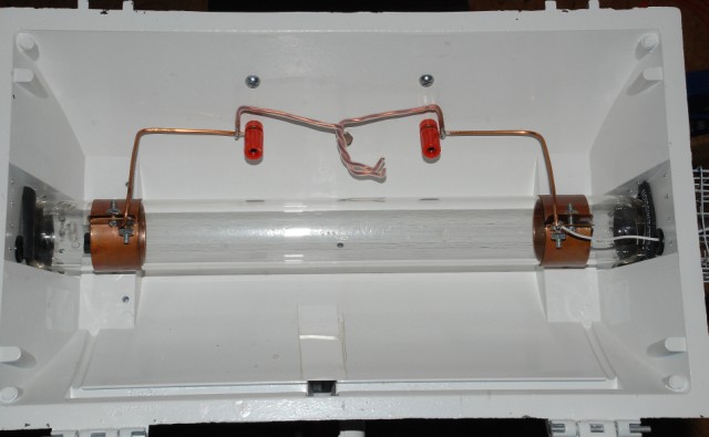
Tube holder assembly with link-coupled matching system.
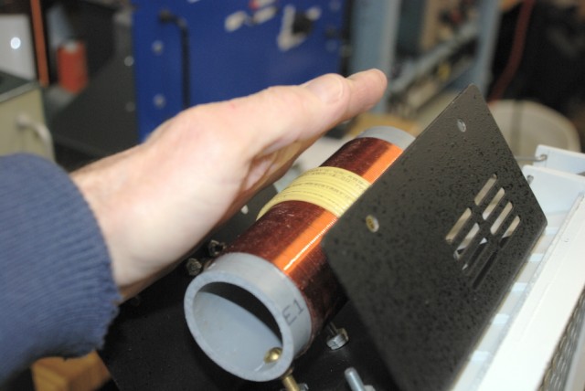
Close-up view of the link-coupled matching system and tube coil.
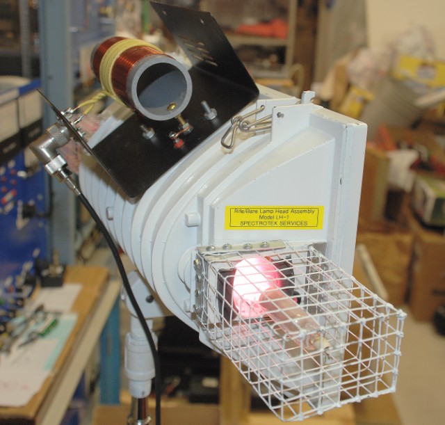
Tube and matching system in operation.
The finished matching system is seen here on top of the tube holder. The coax cable from the RF amplifier goes through the metal wall of the enclosure and connects to the yellow link coil. Leads from the tube coil pass through the top of the tube holder enclosure through the red terminal posts. The tube is being driven by an RM Italy KL-300 amplifier.
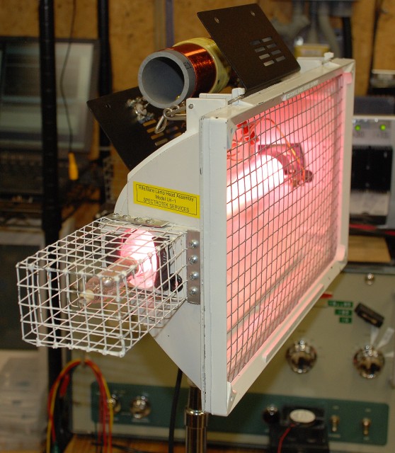
Running at full power. The metal RF screen is in place in front of the tube.
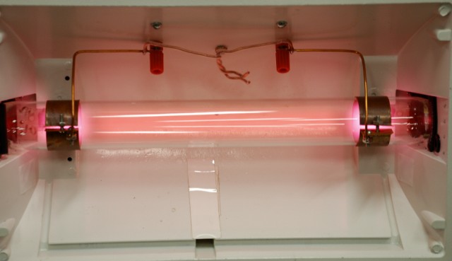
Driven at 10% duty cycle, 200 watts peak power and 20 watts average power.

Driven at 50% duty cycle, 200 watts peak power and 100 watts average power.

Driven at 100% duty cycle, 200 watts peak and average power. Note how the discharge column has started to concentrate into a "core" down the center of the tube. This is typical of plasma tubes driven at high power levels. Also note that the outside rim of the tube holder appears dark in this picture. This is because the tube is so bright, the camera reduced the exposure level to prevent overloading the camera's image sensor. The rim of the enclosure is lit only by the room lights, and so it appears darker in this picture.

This page and all text, data and photographs are Copyright 2012 - 2026 by Ralph M. Hartwell II, All Rights Reserved.