 Rife Plasma System Components Rife Plasma System Components
Information current as of 03 December 2017
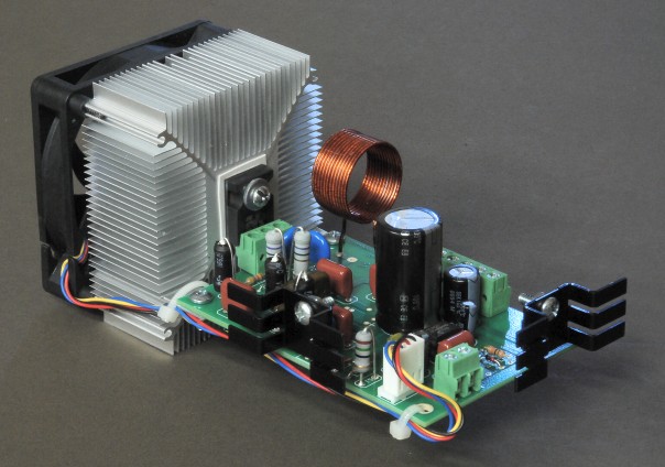
The PA2 amplifier with
the HS2 heat sink.
The price of the PA2 assembled and
tested with the HS2 heat sink and fan is $225.00.
The PA2 plasma tube amplifier may be driven by the SSQ-2F v1.41, the F165, or later models of the GB-4000 frequency generator.NOTE - It may be necessary to add a shielding modification to your GB-4000 when it is used with the PA2 amplifier - see this web page for details.The PA2 plasma tube amplifier is designed to be driven by a SSQ-2F v1.41 processor when the SSQ-2F is set to output a TTL level (0 to +5 volt,) 3.1 MHz square wave square-wave duty-cycle modulated carrier. The PA2 may be driven by any other frequency generator that is capable of outputting a similar TTL carrier signal. The PA2 may also be driven by any frequency generator (such as later models of the GB-4000 or the F165) that outputs a 3.1 MHz sine wave carrier that is square-wave duty-cycle modulated, with a peak-to-peak amplitude of 4.5 to 5.5 volts. The powerful but quiet cooling fan mounted on the rugged HS2 heat sink allows the PA2 to be operated at full power for as long as the researcher desires. A separate power supply for the cooling fan is not needed, because the PA2 provides power for the fan. The PA2 is fitted with the Quick Change option, so the power amplifier MOSFET may be easily and rapidly replaced should the need arise - no soldering is required. Two power supplies are required to operate the PA2, one supply of +20 volts for the logic circuitry and cooling fan, and another of between +50 to +175 volts, depending on the type of plasma tube being used. Please refer to the operating manual for full technical details. The PA2 has been designed so that its output matches a standard 50-ohm load impedance, making it possible to connect the output of the PA2 to a conventional antenna tuner or to the our LC31 coupler system. The PA2 with its innovative design amplifies the high quality signal from the SSQ-2F v3.21. The PA2 increases the power output of the SSQ-2F v1.41 or the GB-4000 or F165 to a power level of between 300 to 500 Watts peak power depending upon the voltage of the DC power supply and the modulation duty cycle. When using a modulation duty cycle of between 0 to 100%, the PA2 will produce at least 300 Watts peak or continuous power output. For a modulation duty cycles between 1 to 50%, the PA2 can produce up to 500 Watts peak power output. These power levels are sufficient to operate even the largest plasma tubes. Please download and read the operating manual for the PA2 before placing your order. It is important to read and understand the information about using an adequate heat sink with the PA2. Although the PA2 is physically very small, it handles a lot of power. Just as with any high power RF amplifier, a substantial heat sink is required for proper operation.
SpecificationsDC Power Supply Input: 1) +15 to +190 V DC at a maximum current of 3.0 amperes. Average operating current less than 2.1 amperes, depending on output power level and modulation duty cycle. 2) +150 V DC required for a nominal peak power output of 300 Watts across a 50-ohm load resistance. 3) +190 V DC required for a nominal peak power output of 500 Watts across a 50-ohm load resistance. Output Load Impedance: 50 ohms. Input Drive Signal: 5 Watts, semi-square wave pulse waveform at 3.1 or 3.3 MHz from the SSQ-2F v3.21. Operating Frequency: 2.8 to 3.8 MHz. Operation outside of this frequency range may cause damage to the PA2. Nominal operating frequency is 3.1 or 3.3 MHz. RF Power Output: 1) The PA2 will produce up to 500 watts peak power, or 250 watts average power across a 50-ohm load when the carrier is modulated by a 50% duty cycle square wave. 2) When operated at a peak power level of 300 watts, the PA2 may be operated with any duty cycle between 0 to 100%. 3) The power output of the PA2 may be adjusted by varying the DC voltage supplied to the PA2. |
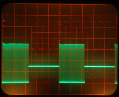
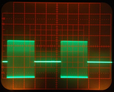
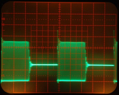
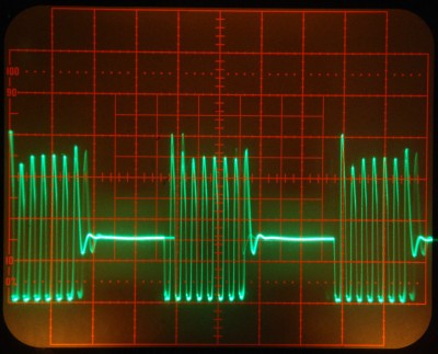
The left side photos are of the PA2 output waveform across a 50-ohm dummy load.
The right side photos are of the PA2 output waveform across a Cheb 8-inch Phanotron tube.
The PA2 was coupled to the Phanotron tube using the 3.1 MHz link coil coupler.
The carrier frequency was 3.1 MHz. The modulation duty cycle was approximately 50%.
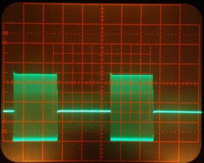
Modulation frequency 20 Hz.
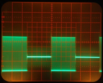
Modulation frequency 2 KHz.
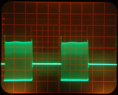
Modulation frequency 20 KHz.
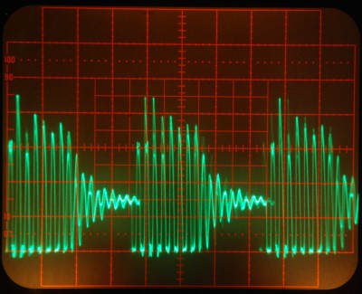
Modulation frequency 200 KHz.
RADIO FREQUENCY WARNING NOTICEThe PA2
is a high-frequency switch mode power supply module designed to furnish
a square wave modulated high voltage alternating current at a frequency
of approximately 3.1 MHz across a 50-ohm load impedance. If the PA2 is
installed incorrectly or used improperly, it is capable of causing
severe radio frequency interference. To prevent this from occurring,
observe the following warnings:
Any
attempt to drive the PA2 with a radio frequency source such as a CB
radio transmitter, will result in either no power output from the PA2
or immediate destruction of the STW20NK50Z MOSFET in the PA2.
|

This web site and all contents including pictures, text and diagrams is Copyright © 2012 - 2020 by Ralph M Hartwell.