First Posted on February 5, 2012
By Ralph M. Hartwell, W5JGV
The use of commercially available RF power amplifiers to drive plasma tubes has been a common procedure ever since Dr. James Bare developed his Bare/Rife plasma tube system. That system, as do most systems, operates on the US Industrial, Scientific and Medical (ISM) frequency allocation of 27.120 MHz. The basic configuration of such systems, is shown in this block diagram:
Most commercial RF amplifiers that have been used thus far have been CB power amplifiers that have been modified to function in continuous duty operation. This usually involved adding one or more fans to cool the heat sink of the amplifier and the ferrite cores in the RF power circuitry of the amplifier. These amplifiers have been used because they will operate efficiently on the ISM frequency of 27.120 MHz, which is close to US CB channel 14, located at 27.125 MHz. The quality of these amplifiers varies widely, and most of them produce terrible signals when used on the air. However, when properly modified and used to drive a Plasma tube, they will often perform adequately.
When researchers began using systems which operated in the 3 to 4 MHz carrier frequency range, different amplifiers were required. While some of the available CB amplifiers would operate at those frequencies, many of them did not have the proper type of ferrite cores to function at low frequencies without failure. Other amplifiers, such as the High Frequency (HF) amplifiers produced by RM Italy have the correct ferrite cores to operate well at frequencies from 2 to 30 MHz, thus making them usable for Plasma tube systems over a wide frequency range. Such amplifiers may be driven properly by the SSQ-2F Plasma System Controller.
Producing high power RF with an amplifier is one thing; coupling it efficiently to the Plasma tube is another. The most common method of coupling the energy from the amplifier to the Plasma tube is by using a commercially available antenna tuner, such as one of the MFJ series of tuners. While this method works, it has several drawbacks. First, tuners (actually, impedance matching systems,) are not 100% efficient in transferring the RF energy from the amplifier to the Plasma tube. Depending on the type of tuner, its adjustment, and local conditions, as much as 10% to 40% of the available RF power may be lost as heat in the tuner. In severe cases, internal tuner components such as coils, switch contacts, etc., may be damaged by overheating.
If you are going to use an antenna tuner, it is better to buy one that is too large rather than one that is too small. If you are using the "standard" modulation method where the RF carrier is modulated by a 50% on/off duty cycle square wave, then remember that the PEAK value of the RF power will be TWICE the AVERAGE power level shown on your power meters. Because Ohmic losses increase as the square of the current, doubling the peak power will double the RF losses during the time the RF power is actually on.
Let's assume that your amplifier can generate 400 watts of AVERAGE power. In that case, with a 50% duty cycle square wave modulated signal, it will be producing as much as 800 watts PEAK power during the RF pulse. Using an antenna a tuner that is rated to handle only 400 - 500 watts will result in excessive losses, tuning difficulties, and unreliable operation as the internal components of the tuner slowly begin to degrade with age and excessive heating. What you really need in this case is a tuner that is rated for 800 to 1000 watts.
Another problem in choosing the correct antenna tuner is that the advertising wizards who write the description for these antenna tuners tend to stretch the truth just a wee bit. Many tuners will be described as being able to handle a full 1,000 watts (1 KW) of power, however a closer reading of the data sheet shows that that is only for 1,000 watts of single sideband (SSB) speech energy, which is roughly 33% of 1,000 watts, or about 333 watts, on an average basis. And that's with the tuner cooling down between transmissions, which usually happen on a 1:3 transmit to receive ratio.
What does all this mean? Simple. If your RF amplifier is putting out 800 watts of peak power, or 400 watts average power, that 1,000 watt rated tuner can only handle about 350 watts average on a continuous duty basis, which is what it will be doing when you run those 1-hour long frequent sessions. You should use a tuner rated for 1,200 to 1,500 watts SSB duty service. And they are not cheap. Of course, if you have an amplifier that can produce more RF power than is required to properly drive your Plasma tube, you may be able to use a smaller, less expensive antenna tuner and simply ignore the additional losses. But that's not all...
The antenna tuners commonly used are manufactured for Amateur Radio service. That means they are designed to do two specific things. (1) match the 50 Ohm output of the transmitter to the unknown impedance of the antenna system, and, (2) eliminate harmonics of the RF carrier. Foe Plasma tube use, matching impedance is great, but eliminating harmonics is not! When we are driving a Plasma tube, we want the rise and fall times of the RF pulses to be as fast as possible, and the narrower the bandwidth of the matching circuit is, the slower will be the rise and fall times. In fact, the better the antenna tuner, the worse will be the rise and fall times because of the elimination of harmonics. An antenna a tuner can only make an accurate impedance transformation on the specific carrier frequency it is tuned to, frequencies above and below the carrier frequency will be reduced in strength. This is NOT what we want to happen in a matching network. But we can fix that. Read on...
The underlying use of an antenna tuner in an RF transmission system is to make the transmitter "see" a 50 Ohm load by converting the unknown impedance of the antenna to a value of 50 Ohms. This results is a VSWR (Voltage Standing Wave Ratio, usually abbreviated as SWR,) of 1.0:1. Note than in practice, this is never achieved, but most amplifiers are perfectly happy with a VSWR ratio of as high as 2.0:1, and will put out power quite happily at that VSWR. So, if we can manage to couple energy from the amplifier to the Plasma tube with low losses, and obtain a VSWR of less than 2.0:1, everything should be happy and play nice. Can it be done? Yes.
Here is a block diagram of this system using the SSQ-2F as the RF source. Note that it is quite similar to the Bare/Rife 27 MHz system, but the antenna tuner has been replaced by the link coupling system.
The method shown here is simple to implement. It utilizes a simple transformer step-up between the RF amplifier and the Plasma tube to match the impedance between the amplifier and the tube, while at the same time using the principle of resonance to achieve a high voltage for initially starting the discharge in the tube at the beginning of each RF pulse. The circuit diagram of the link coupler is shown in the diagram below:
This is a simple link-coupled, air-core transformer system that matches the resistive impedance of the Plasma tube when it is conducting to the resistive impedance of the RF amplifier. The link coil is the coil connected to the RF amplifier - in Amateur Radio terminology, it "links" the transmitter to the matching circuit. The matching coil (let's call it the "tube coil",) has about eight time as many turns on it as does the link coil. This causes both an impedance and a voltage step-up between the RF amplifier and the Plasma tube. This turns ration results in roughly a 1.5:1 to 2.0:1 VSWR at the amplifier when the tube is lit. Most amplifiers will tolerate that level of VSWR just fine. The VSWR may be reduced further by using a series variable capacitor in the link circuit, but for the most part, this is an unneeded complication and expense. Variable capacitor C1 should be as small as possible. If the coil is designed correctly, the capacity of the plasma tube and its connecting wires will provide the necessary capacity to tune the coupler to resonance.
If you have a 400 watt peak power RF amplifier, then it will generate about 141 volts at the 50 Ohm output connector. With a voltage step-up ratio of eight to one in the coupling system, theoretically, about 1128 volts will appear at the terminals of the Plasma tube. Since most Plasma tubes require between 700 to 1500 volts to start the discharge, this may be enough to light the tube. However, because this is an air-core transformer, the magnetic field coupling is much less than it is in an iron core transformer, so the actual voltage step-up is considerably less than eight times. However, we can increase the voltage considerably by resonating the tube coil. We can do this by carefully adjusting the number of turns on the tube coil so that the coil has enough inductance and self capacitance between its turns so that when the extra capacitance of the connecting wires and the tube electrodes are added, the coil will self-resonate at the desired carrier frequency. This resonance will greatly increase the voltage appearing at the tube electrodes before the tube lights up. Using the system I am describing in this document, I am able to light the tube seen in the photographs below with as little as 20 watts of RF power.
When the coil is correctly designed and constructed, only a very small amount of additional tuning capacity is needed. On this 3.1 MHz system I needed only about 5 pF of additional tuning capacity. I was able to obtain that by using a simple pair of Teflon tube insulated twisted wires, just like the old "gimmick" capacitors one used to see in radio receivers.
We do not want to add any more capacitance across the coil than is absolutely necessary. We want to minimize the capacitance (C) and maximize the inductance (L.) By using a large L and a small C, the circuit has a lower Q value than if a normal tuning capacitor is used. This is good, because a high Q circuit suppresses harmonics, while a low Q circuit passes them more easily. Using a coupling circuit with a low Q increases the speed of the rise and fall times of the RF pulses.
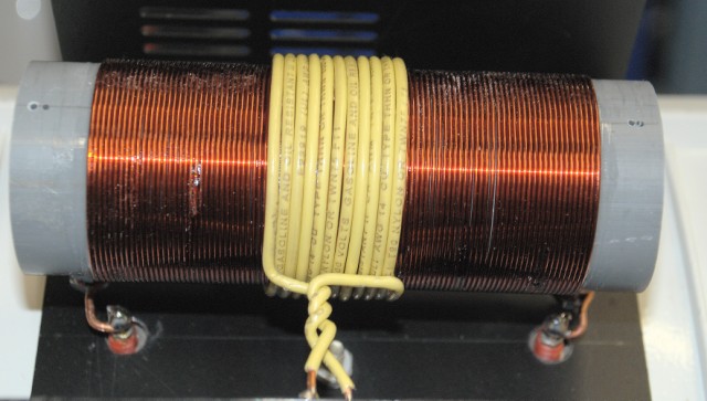
The yellow link coil is wound over the larger tube coil. The coil form is a length of PVC plumbing pipe. The link coil consists of 11 turns of #14 AWG insulated copper wire. The tube coil consists of 93 close wound turns of #18 AWG enameled copper wire. The coil form is a 6" long length of 2" OD PVC plastic plumbing pipe.
Using the program SOLNOID2.EXE (it runs in a DOS window) design a tube coil that will resonate at the carrier frequency (in this case, 3.1 MHz,) with no more than about 20 pF additional external capacitance across the coil. If you use a close-wound coil (no space between adjacent turns) the coil's self-capacitance will be highest. This will result in a coil with the smallest amount of wire and the lowest Ohmic losses. A value of 0.95 for the (R) Ratio wire Dia/Pitch should be used when entering data into SOLENOID2.EXE.
Now use SOLNOID2.EXE to design the link coil. It should be made of at least #14 AWG wire. Wire with PVC, THHN, of THHW insulation will effectively be double-spaced as far as SOLNOID2.EXE is concerned. A value of 0.5 for the (R) Ratio wire Dia/Pitch should be used when entering data into SOLNOID2.EXE. Adjust the number of turns on the link coil until the impedance of the link coil is between 70 - 150 Ohms. You should now have a coupling system that has a turns ratio of between 6:1 and 10:1. Anywhere in that range should work satisfactorily.
The tube coil you just calculated should work well with connecting wires to the tube of no more than about 24 inches per lead. After mounting the matching network and the tube, it's time to tune the system.
Using a square wave modulated RF signal, use the GAIN control on the SSQ-2F to adjust the duty cycle of the square wave until you apply enough power applied to light the tube, then increase it just a little bit more than that. Now, carefully place your hand parallel to the coil and move your hand closer and further from the coil, as shown in the picture, below.
If moving your hand closer to the coil makes the tube brighter, you need more capacity across the coil, or you may squeeze the coil turns closer together to increase the inductance.
If moving your hand closer to the coil makes the tube dimmer, you need less capacity across the coil, or you may spread the coil turns further apart to decrease the inductance.
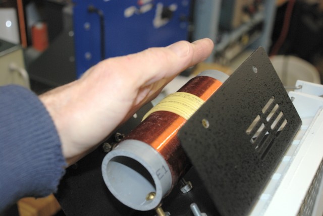
Tuning the coil "by hand."
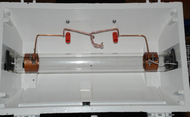
The twisted Teflon insulated wire "tuning capacitor" is connected across the Plasma tube electrodes. This tube uses external copper collar style electrodes. The red binding posts connect to the ends of the tube coil on top of the tube holder.
The finished matching system is seen here on top of the tube holder. The coax cable from the RF amplifier goes through the metal wall of the enclosure and connects to the yellow link coil. Leads from the tube coil pass through the top of the tube holder enclosure through the red terminal posts. The tube is being driven by an RM Italy KL-300 amplifier.
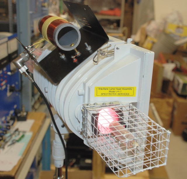
Running at full power. The metal RF screen is in place in front of the tube.
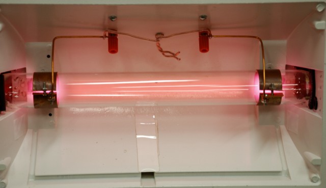
This shows the tube driven with a 200 watt peak power, 20 watts average power, 10% duty cycle using a SSQ-2F Control Board and the KL-300 amplifier.

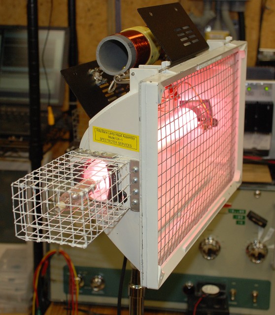
Driven at a 50% duty cycle, 200 watts peak, 100 watts average power.

Driven at 100% duty cycle, 200 watts peak and average power. Note how the discharge column has started to concentrate into a "core" down the center of the tube. This is typical of Plasma tubes driven at high power levels. Also note that the outside rim of the tube holder appears dark in this picture. This is because the tube is so bright, the camera reduced the exposure level to prevent overloading the camera's CCD chip. The rim of the enclosure is lit only by the room lights, and so it appears darker in this picture.

This page and all text, data and photographs are Copyright © 2012 - 2018 by Ralph M. Hartwell II, All Rights Reserved.